2.2. Assembly instructions
ESP-12 breadboard adapter requires basic to intermediate soldering skills to assemble. If you have some experience with soldering THT and SMT elements to the printed circuit boards you won’t have any troubles assembling the adapter. Those who don’t feel confident please consult an illustrated step by step guide below.
Recommended soldering order is:
- ESP-12 module,
- Pull-up / pull-down resistors (optional),
- Pin headers.
Hint
Typical assembly time is 1 hour.
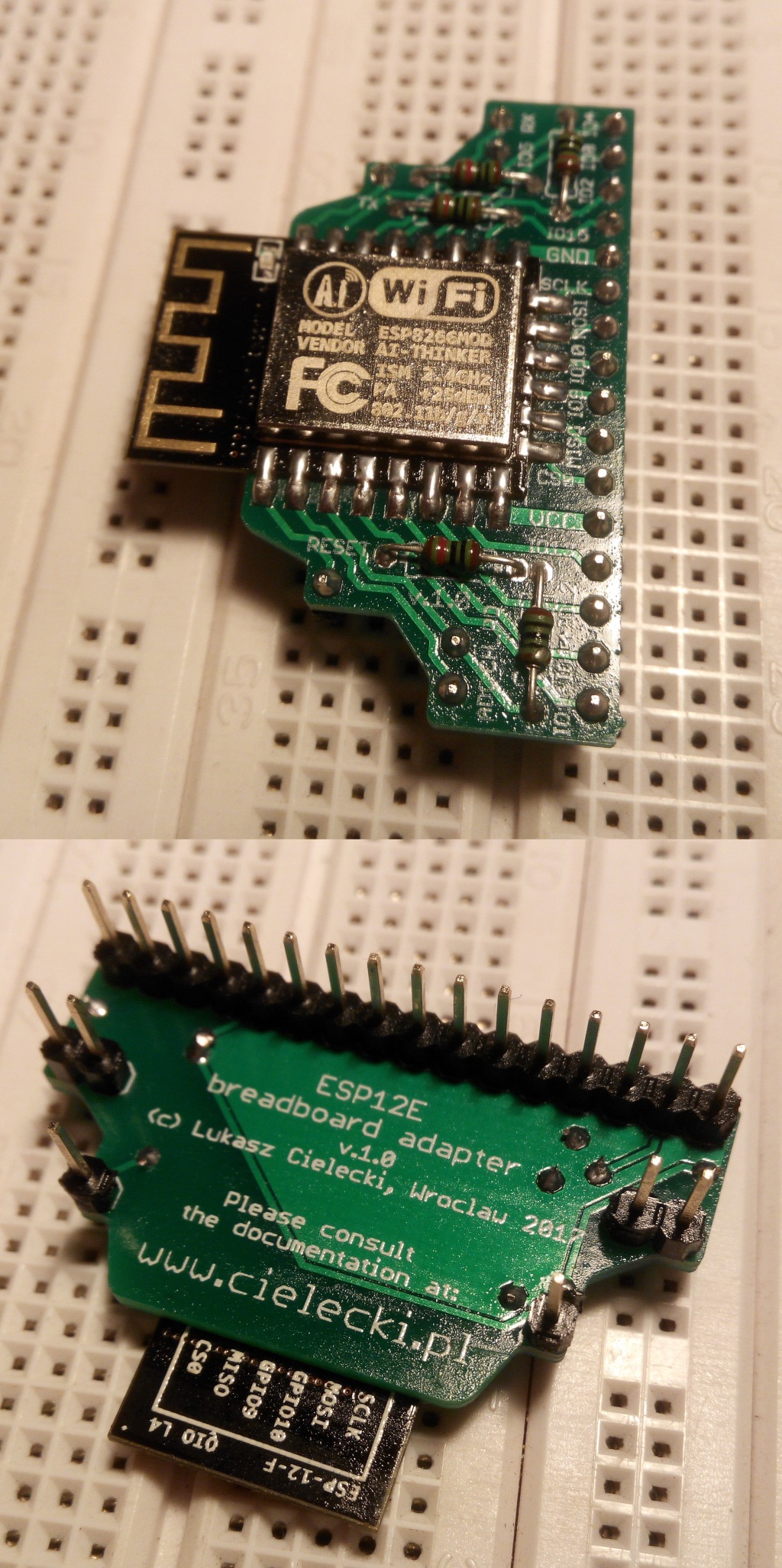
2.2.1. Step-by-step soldering instructions
Note
If you’re left-handed then while soldering ESP-12 module (SMT) you’d rather use TX signal pad whenever RESET pad is mentioned.
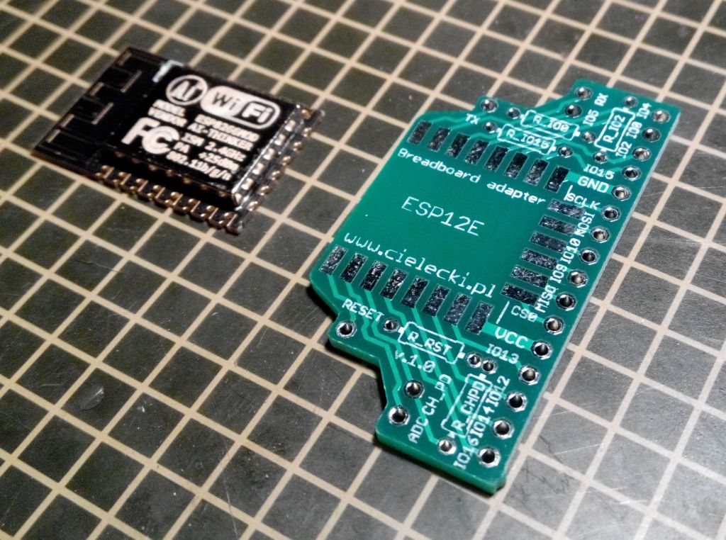
Prepare your ESP-12 module and a breadboard adapter board (PCB). Depending on the solder you have and your personal preferences you may put some flux (rosin) on PCB pads.
Using your soldering iron transfer some solder on a RESET signal pad and then put some extra flux on top of it.
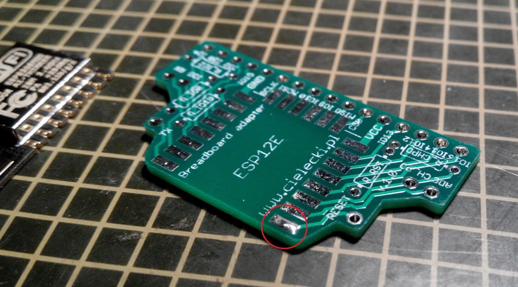
Align precisely your ESP-12 module on a PCB. Use RESET, VCC and GND pads as guidance points.
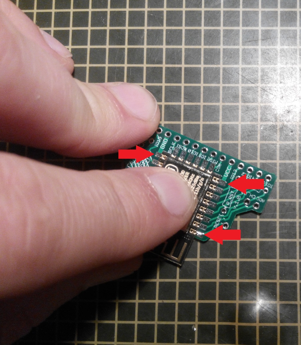
Holding the ESP-12 heat up the solder on the RESET pad to fix the module position on the PCB. Check its align. If it needs to be corrected add more flux to the RESET pad and heat the solder up again to make ESP-12 perfectly aligned. When position looks fine go to the GND pad and solder it. When it’s done go back to the RESET pin and replenish solder to the normal amount. Then proceed with other pads.
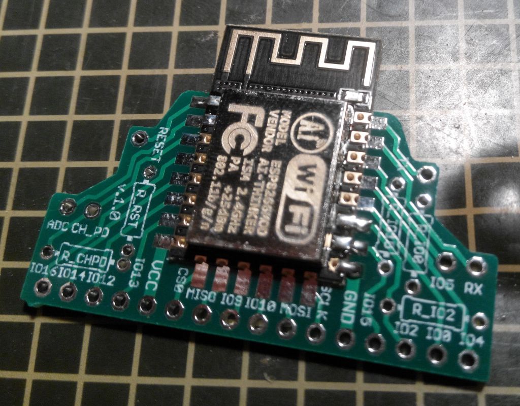
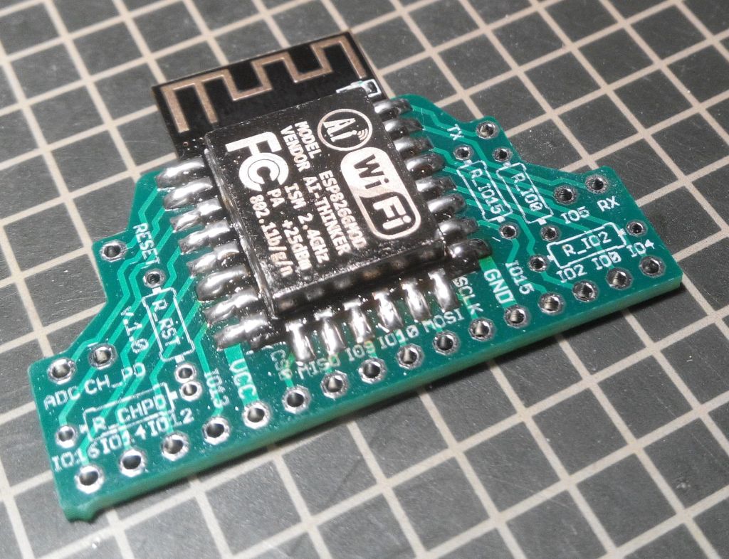
Finish soldering all the ESP-12 pads.
Hint
If you add too much solder and you accidentally connect two nearby pads together, don’t worry. Simply add some flux, heat the solder and use desoldering pump (solder sucker) to remove some solder.
Now it’s time to solder all the resistors (this is the optional part). Insert components and splay their leads to keep them in place.
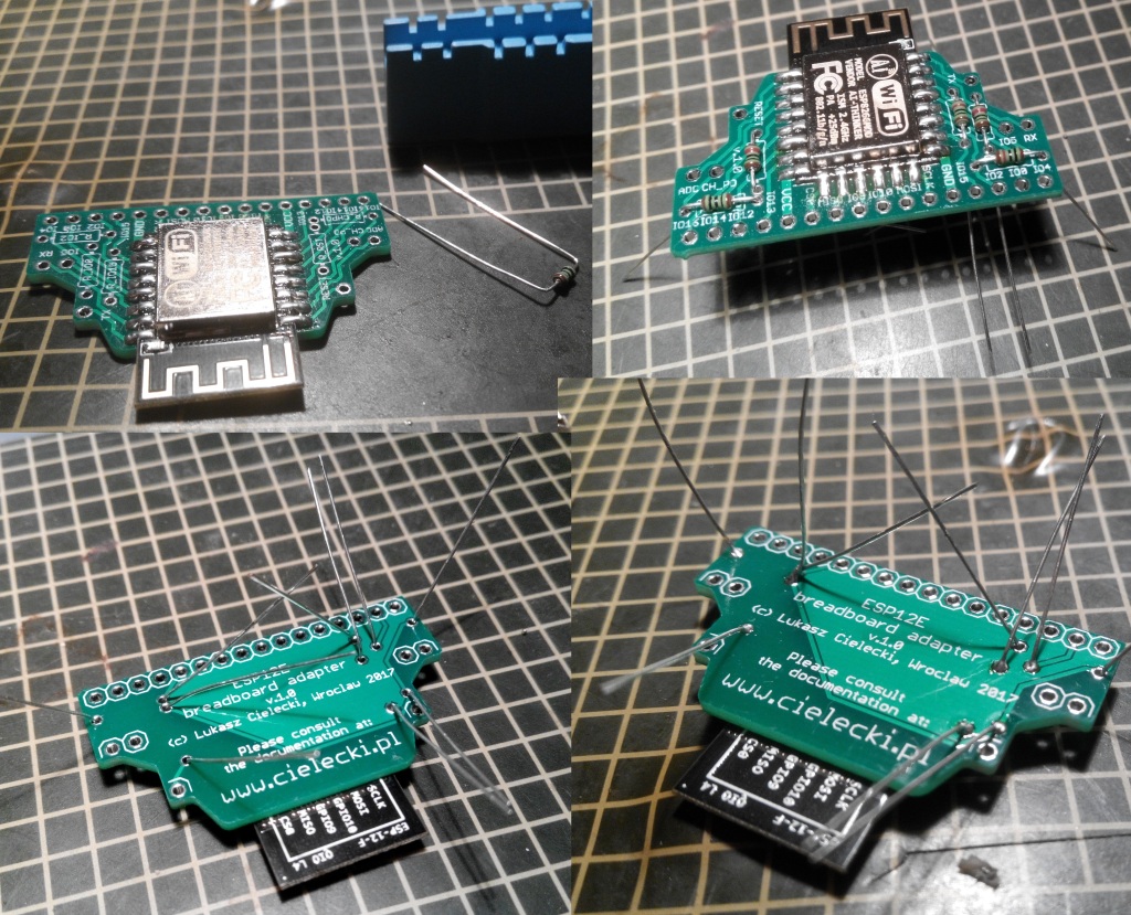
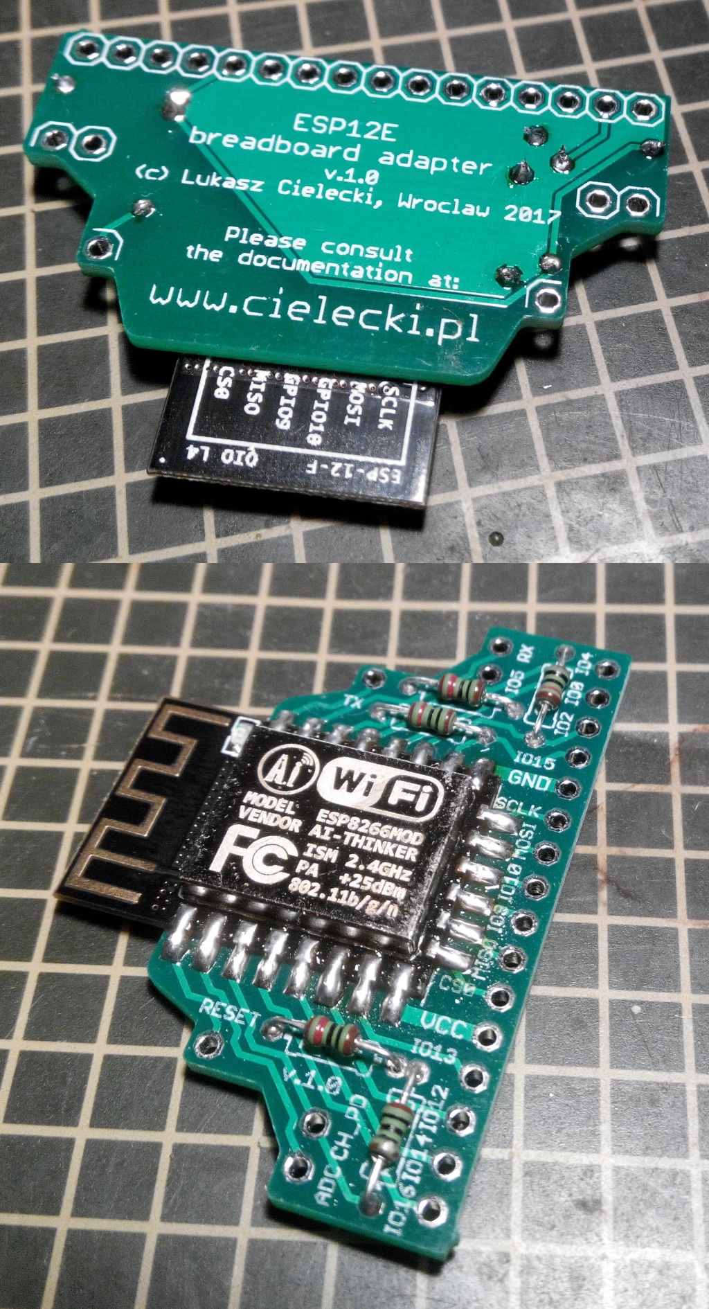
Solder all the THT resistors and remove their leads.
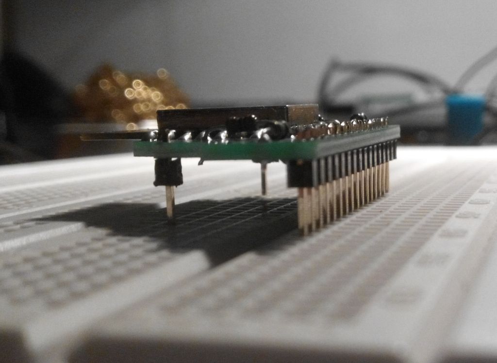
Prepare pin headers for soldering. It’s very important to align them exactly perpendicular to the PCB. Using actual breadboard may help you with this.
Warning
If you use a breadboard to align the pin headers do not push the adapter down into the contacts until you soldered all the pins. Solder on a breaboard as short as possible to avoid transferring heat to it. Only use this method to fix the position of a pin strip by soldering two ending pins and finish on the other surface.
Start pin header soldering from RESET, TX, IO16 and IO4 pins.
Finish by soldering all the pin headers. It is recommended to clean the PCB with flux remover.