1. Introduction
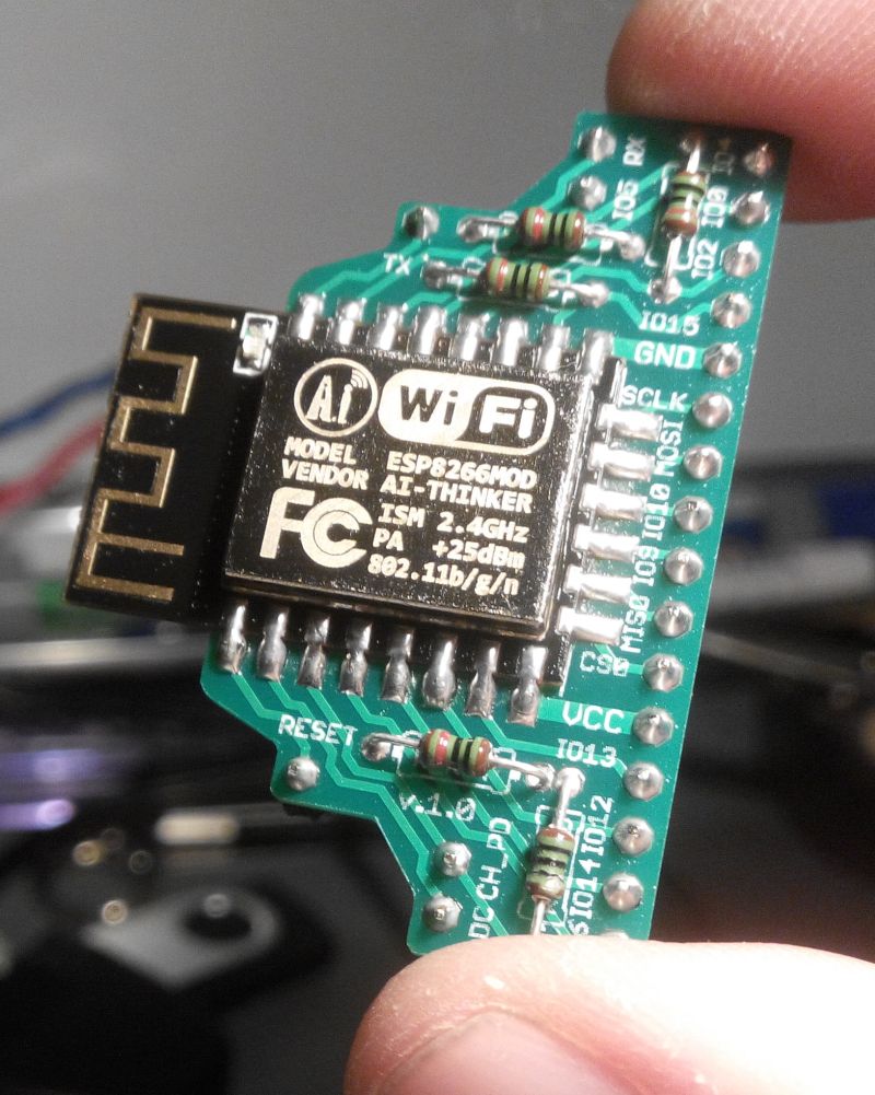
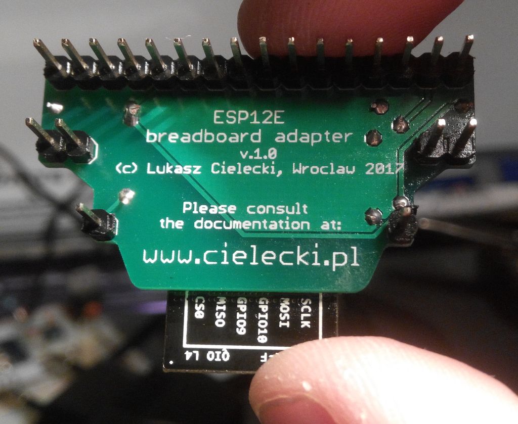
ESP8266 ESP-12 breadboard adapter enables you to use popular ESP-12 modules with standard solderless breadboards with 2.54 mm (0.1 inch or 100 mil) clip raster.
It’s targeted mainly for designers who want to quickly test their ESP8266 prototypes and do not need complicated ESP8266 kits. The main idea was to create fully featured breadboard adapter that includes only components usually present across all ESP designs (but even these are optional) and puts absolutely no constrains on your project. Therefore it’s rather more practical than educational.
Following goals are achieved:
- It breakouts every single pin of ESP-12 module. That includes SPI interface and GPIO9 / GPIO10 available on ESP-12 E and F versions.
- It’s ready for optional THT pull-up / pull-down resistors for RESET, CH_PD, GPIO0, GPIO2 and GPIO15 pins. That saves space on a breadboard for the part of the design that is unique also making reset and flash mode switches circuits as easy as possible. If you choose not to use pull-ups / pull-downs then the pins are simply directly broken out to the breadboard. THT (Through-Hole Technology) was chosen for resistors to make DIY soldering easier.
- Small size - only 16 rows of breadboard is occupied.
- All signals are available at uncovered breadboard tie points. As a result you don’t need to route all signals before plugging adapter into breadboard or remove adapter to route a new signal.
More practical - less educational approach is also expressed by what’s not included onboard:
- No voltage regulator since you probably can’t choose one voltage regulator for all your future designs.
- No FTDI like interface since you probably won’t include this in your final design - it’s more economical to use one serial port interface for all your designs.